James River Pulp Millby Jamie Walls, InterSol Engineering Inc., Colin Alston, Alston Associates Inc., |
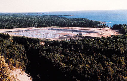
| Introduction New provincial and federal guidelines for treatment of industrial waste that took effect in December 1995 mandated the construction of a secondary wastewater treatment facility at James River, Marathon Limited's pulp mill in Marathon, Ontario. The mill site is located on the north shore of Lake Superior, approximately 300 kilometres west of Thunder Bay, Ontario, Canada.
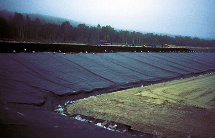
The new treatment facility includes a large secondary treatment basin which is 375 m long x 278 m wide x 5 m deep. The secondary pond has an outside perimeter length of 1.4 kilometres, with 30 m long side slopes at 3.5H:1V. The side slope of the lagoon is lined with 80 mil high density polyethylene (H.D.P.E.) geomembrane, cushioned with a needle punched nonwoven geotextile. The side slope liner keys into a 300 mm thick sand-bentonite base liner. A concrete infilled geocell lining system was used to cover the upper zone of the side slopes and protect the geomembrane liner from environmental damage, such as ice abrasion, wind and wave action, vandalism and possible damage from aerators if they were to become detached from their moorings. The protection system also had to have sufficient mass to withstand negative pressures from wave action and thus maintain stability in the near surface soil of the earthen slopes. Nonwoven geotextile separates the concrete infilled geocell from the underlying H.D.P.E. liner.
Design Considerations Protection systems that could have been considered included reinforced concrete, rock riprap and cabled concrete block systems. A reinforced concrete cover system would require forming on top of the geomembrane, which would therefore increase the risk of damage (i.e. puncture) to the liner during construction and increase the cost of construction. Rock riprap was rejected since the size of rock required would be too difficult to place without damaging the geomembrane. Unless a wide midslope berm was to be constructed, riprap would also require full, or partial coverage of the bottom of the pond to provide passive resistance to sliding on the side slopes. A cabled concrete block system was considered since it could be anchored at the crest of the slope and, with proper care, could be placed without damaging the geomembrane. However, concerns about the constructability of a cabled concrete block system on top of the geomembrane outweighed potential cost savings over some of the other alternatives. Material Specifications for the Slope Cover System The tendon selected to anchor the geocell protection system was a round braided cord consisting of a parallel filament inner core covered with 32 strands of braid. The cord material was high tenacity polyester continuous filament yarn which was covered with a protective coating of extruded polyethylene. Specifications for the concrete infill were balanced to facilitate placement in the geocells on the 3.5H:1V slopes and long term durability under the prevailing climatic conditions. The specifications called for a minimum compressive strength of 20 MPa with 6% air entrainment and a slump of 100 mm " 25 mm. Construction The general sequence of the construction was to first excavate the anchor trench and place the pipe for the deadman anchor system. Tendons were then cut to measured lengths that included the length of the expanded geocell sections, with a suitable allowance being made for knots and extension to the bottom of the anchor trench. The tendons were inserted through the pre-drilled holes in the geocell sections in sufficient numbers to satisfy the design tensile strength requirements. Knots were tied on short lengths of PVC rod at the downslope end of the geocell sections to hold the tendons in place as the geocells were expanded into position. Geocell sections were then expanded down the slope and held in position with sandbags, top and bottom. Adjacent sections were mechanically joined by interleafing the ends of outside cells and stapling them with a pneumatic stapler. Toward the end of each day, the crew would tie all tendons around the pipe, backfill the trench and install the PVC restraint pins in each of the top cells of the geocell sections. The restraint pins were inserted through a double, self-knotting, loop in the tendons. Concrete was then placed in the installed geocells using a track backhoe and a concrete skiff and given a float finish. L&W For more information on this project, contact: |
©2000, 1999, 1998 Land and Water, Inc.