Vegetated Channel System Protects Eroded Stream Bank |
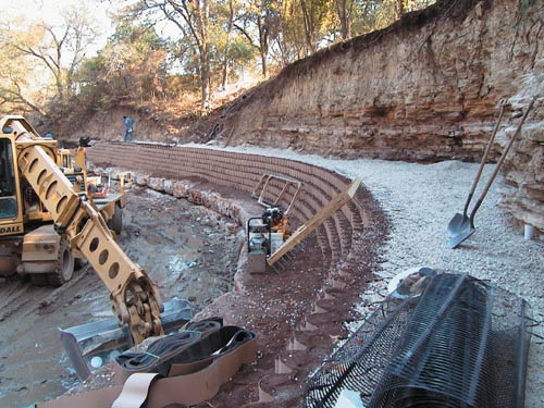
 Engineer Mike Kelly, City of Austin, inspects damage of West Bouldin Creek caused by erosive effects of focused flows at a 90-degree turn. Photos by Soil Stabilization Products Co. In the summer of 1999, West Bouldin Creek in Austin, Texas had experienced significant erosion of a 150-foot long, 22-foot high section of a bluff adjacent to the South Sixth Street roadway. At this location, a near 90-degree turn in the creek created focused flows and erosive forces that severely undercut the outside bank of the creek. The concentrated flows had caused undermining of the embankment to the point where emergency repair had to be implemented before the roadway was impacted. The erosive shale foundation soils combined with a significant overburden of limestone complicated the problem. The City of Austin' s Watershed Protection Department personnel were charged with solving the problem quickly and completely. We wanted a long-term solution that would resist further erosion of the bluff while maintaining the natural appearance of the stream bank," said Watershed Engineer, Mike Kelly. Initially, the engineers considered a conventional gabion design that requires manual labor to fill individual baskets with stone and tie them together with galvanized wire. However, they discovered this process would not only require significant manpower, it would drastically alter the stream environment and aesthetics. Moreover, there was some doubt that the gabion design would solve the problem long term. "That' s when we turned to Soil Stabilization Products Co. (SSPCo), Inc. for advice on the feasibility of a vegetated geocell wall to solve our problem," said Kelly. "After reviewing the site soil conditions and desired aesthetics with the City of Austin, we suggested a composite wall design integrating Presto' s Geoweb® earth retention system and geogrid reinforcement to provide additional structural integrity and protection of the embankment from future erosion," said Mel Lee, Project Coordinator at SSPCo. "This system is specifically designed to meet the challenges of change-in-grade construction situations like this one, and to offer a long-term solution to difficult erosion control problems. Recognizing the city' s desire for a natural look immediately after construction, we also suggested a sand-colored facia which would blend in well with the native soil and rock while the vegetation was getting established." According to Lee, a geocell earth retention structure is a near vertical wall constructed of erosion resistant materials interposed between the erosive soils and the water flows. The system is engineered to be structurally stable under known externally imposed loads. Its multi-layer design makes it very adaptable and capable of meeting a wide range of retaining wall application requirements. Classic methods of stability analysis can be applied to evaluate a broad range of infill, backfill and surcharge parameters. Key criteria for the selection of an appropriate geocell retention structure design include the project site soil conditions, availability of suitable backfill materials, project economics and the desired aesthetics of the completed site.
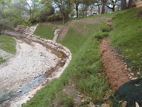
The geocell system is an engineered, polyethylene honeycomb-like network of interconnected cells that stabilizes soils through confinement. Resistant to naturally occurring chemicals, the system eliminates any potential for cracking, spalling, splintering or corrosion that typically affects concrete, steel and timber-based earth retention systems. Depending on specific project requirements, a variety of infill materials can be used with the geocell earth retention system, including granular materials, concrete or topsoil with selected vegetation. In addition to the sand-colored geocell fascia panels used to provide a natural appearance during revegetation, the West Bouldin Creek wall design takes advantage of a number of other innovations. Cell wall perforations in the interior cell walls allow lateral drainage through the system and access to any naturally occurring moisture. Surface and subsurface drainage are incorporated in the design to prevent the build-up of hydrostatic pressures at the back of the geocell facia. Horizontal terraces are formed between geocell layers where vegetation can take root and flourish in the topsoil of the outer cells. A 3' h wall batter or setback was specified to accommodate native shrub plantings of sufficient size to speed maturity of the plantings. The geocell system' s flexibility allowed the wall structure to conform to the inherent curves and contours of the creek' s landscape and accommodate potential settlement without loss of structural integrity. In addition, the ability of the geocell sections to accommodate obstructions enabled a natural blending of the wall system with the prominent rock outcroppings on either side. An internal stability analysis was provided by Presto' s consulting engineer, InterSol Engineering. With InterSol' s preliminary design, City of Austin engineers were able to corroborate their own analysis and design a structurally sound, cost-effective wall system incorporating geogrid reinforcement. In composite wall designs, geogrid reinforcement layers are integrated at various layers as a tie-back method with the geocell system to provide structural integrity. In this case, the reinforcement layer was placed every three geocell layers, or two feet. "The geogrid reinforcement was designed to withstand a long-term allowable design load (LTADL) of 1000 lb/ft," explains Jamie Walls, InterSol Engineering. "The LTADL refers to the allowable load after factors of safety for creep, construction damage and chemical/biological durability have been applied. "We were working with an existing slope angle of 87° and proposing a 72° inclination of Geoweb facing. The maximum wall height was 6.7 m (22 ft) with a maximum available base width of 2.4 m (8 ft). Conventional design procedures for reinforced segmental walls require a minimum base width (i.e. reinforcement length) of 0.6 times the wall height (or 4.0 m (13.2 ft) in this case). Since the existing slope was considered to be internally stable, if protected from further erosion, conventional design procedures for reinforced segmental walls were not applicable for internal and external stability analysis of the proposed gravity structure (i.e. geocell cellular confinement system and reinforced backfill soil). Instead, 2-part wedge analyses were carried out to determine reinforcement requirements to prevent outward sliding of the geocell facia and the stability against sliding of the entire reinforced soil mass. The connection capacity between the reinforcement and geocell facia was checked by calculating the shear resistance between the geogrid material and the geocell granular infill."
"Installing the geocell system is a user-friendly process that proved to be much less labor-intensive for our crew than conventional methods," said Kelly. He estimates that the four-month construction of the geocell earth retention system was performed at one-half the cost of other options, such as concrete wall structures or gabion basket designs. Although a summer of extreme drought for the Austin area followed immediately upon construction, City of Austin engineers report that more than 60 percent of the plantings in the cells have survived. The cellular environment helped manage the available water for the benefit of the vegetation. "This technology is a valuable tool in our constant quest to stabilize slopes while presenting a naturally vegetated wall face to the public," offers Kelly. "We will continue to explore other applications of geocell systems on future projects." L&W For more information, contact Samuel Randolph, Soil Stabilization Products Co. (209)383-3296 or Daniel Senf, PE, Presto Products Co., (800)558-3525. |
©2001, 2000, 1999, 1998 Land and Water, Inc.