Advancements in Tube Technology for Riverbank Stabilizationby Douglas A. Gaffney, P.E. |
|
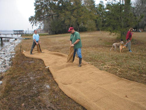
 Deploying reinforcement apron. Introduction The two highlighted projects also demonstrate the use of geotextiles, both natural and synthetic, for strengthening the saturated, soft foundation under the main tube. These projects combine geotechnical engineering with riverbank and bluff restoration design techniques. Cohansey River, New Jersey Bluff erosion can be caused by several factors such as ground water seepage, overland runoff, currents and wave attack. It was determined that the primary reason for the progressive erosion was waves attacking the base of the bluff resulting in instability and eventual sloughing of the bank. The design of a protective structure for the bluff would need to prevent erosion of the base and stabilize the bank. The top of the bluff is approximately 25 feet above the river. The site includes a residence and a high bluff, 500 feet in length, consisting of sands, clays and loess. The geology is coastal in origin and the interbeds of cementous sands cause clefting at the base of bluff in many locations. The bluff is migrating towards the residence, unoffical measurements of the bluff failure is in the order of half a foot per year. The failure has caused the bluff to be devoid of vegetation and generally be an eyesore for the property and patrons of the river corridor. The geometery of the Cohansey River at this location creates an erosional “hot spot.” The mixture of the river flows (base and storm) and the tidal backwash of the Delaware Bay cause severe erosion at the base of the bluff. The northern bank of the river is heavily buffered by a wetland marsh complex, along with similar marshes directly upstream of the failing bluff and fully vegetated slopes directly downstream of the bluff. Therefore the solution was to be visually compliant with the surrounding properties and ecosystems and also protect the adjacent property from further land loss. The tidal range at the project site is approximately 4 feet with Mean High Water (MHW) occurring at +3.0 feet North American Vertical Datum (NAVD) 1988. The base elevation for the tubes was 0.0 feet NAVD 1988 and the tubes would be filled to a top elevation of +5.5 feet NAVD. At high tide, the construction site is underwater, therefore several aspects of the project would have to be completed during low tide. The work area at the base of the bluff was very narrow, saturated and very soft in spots. Additionally, river currents could be expected during the winter season. Since the primary cause of the erosion was sloughing of the bank, a structure was required which could withstand wave attack and associated overtopping. Studies were completed to determine the magnitude and mode of failures available to the site. The most important part of the study was to determine the local ambient water conditions. The cause of slope erosion was analyzed for wave action due to aeolian (maximum fetch) and mechanical (boat wake) effects. Since the river was at one time navigable, it was reasonable to consider both cabin cruisers and tugboats for design purposes. The wind driven waves consist of two major components, the wind quality and the fetch. The wind quality consists of maximum wind speed, direction and duration. Wind speed and direction are determined from the fastest mile wind speed isoval maps presented by Thom (1968). The 100 year fastest wind speed is about 100 miles per hour. The longest fetch at the particular river geometry was determined to be 1,000 feet in the downstream direction and 1,300 feet in the upstream direction (Gaffney and Merl, 2002).
Maximum wave heights and periods were calculated based on the forecasting equations given in the Shore Protection Manual (USACE, 1984). The maximum wave period and height for wind blowing downriver is 1.8 seconds and 1.87 feet; for wind blowing upstream the wave period is 1.7 seconds with a corresponding wave height of 1.76 feet. Several structural options were considered. A cost comparison of designs utilizing rock, gabions and sand-filled geotextile tubes was conducted. The narrow work area, construction access restrictions and cost of materials favored the geotextile tube option. There was very little room to work at the river’s edge, and bringing construction materials to the site was not a trivial concern. The contractor, Coastal Management, Inc., was sensitive to the property owner’s desire to not destroy landscaping at the top of the bluff. The use of tubes allowed minimal disturbance and the ability to work from the land.
Geotextile tubes, when uncovered, are susceptible to debris damage. In recognition of this, several designs were considered to armor the tube. A woven, vinyl-coated, polyester fabric was chosen for its durability and aesthetic properties. The durable protective fabric was sewn to the geotextile tube on its exposed face, in the factory. Other protective layers have been used on tubes in the past. Nonwoven polypropylene has been used in similar applications, but the fabric is black and does not have the abrasion resistance to survive in a dynamic environment. Woven polypropylene is presently being used on some projects in Texas, but the black color is an aesthetic disadvantage. Prior to installing the tube, a scour apron was to be deployed at the base elevation. During the grading of the foundation, a localized area of extremely soft, saturated soil was found. Sand was placed in the soft spot, but the soil strength could not be improved sufficient to carry the weight of the equipment. A geotextile separation and reinforcement fabric was deployed and a six inch layer of sand placed above the geotextile. This allowed a 28-ton bucket loader to finish grading the foundation. A small trench near the bluff was dug to provide stability to the tube while filling. The scour apron was deployed within the trench, extending toward the river. An anchor tube was filled with sand at the river’s edge. The tube was then deployed and filled using a combination hydraulic – mechanical filling technique. A hopper, fitted with a hydraulic pump, located on top of the bluff created the sand slurry which was pumped into the tube. After filling the tubes to the desired height, the bluff was graded, and covered with a woven coir mat over a nonwoven coconut erosion control blanket. Ivy was then planted into the bluff face. Another benefit of the vinyl-coated polyester protective layer was that the fill ports could be glued closed using commercially available PVC adhesive. Typically, fill ports are either sewn shut or tied. The summer of 2002 was very dry, and much of the ivy did not survive. Nonetheless, when late summer conditions improved, native vegetation began covering the slopes, and integrating the sand-filled tube with the bluff.
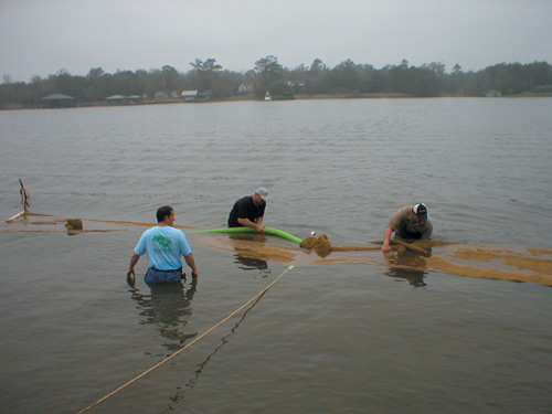
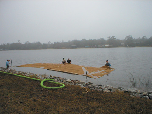
Dog River, Alabama With the increase in boat traffic on the Dog River in Alabama, much of the river’s shoreline is armored with bulkheading or riprap. These shoreline treatments hinder natural vegetation from growing, due in part to the reflection of boat wake energy. This project was one of two restoration projects intended to demonstrate methods of increasing vegetation along the shoreline. The purpose of the tube breakwater was to absorb some of the boat wake energy to allow vegetation to become established. The tube was placed approximately 20 feet off shore, and was 40 feet long, 13-feet in circumference and manufactured from coconut, jute and cotton. Large sand-filled tubes are much heavier than fiber-filled products such as coir logs. Coir logs are appropriate for lower energy environments, and their stability is directly related to how well they are anchored. In contrast, sand-filled tubes are “anchored” by weight. The 13 foot circumference tube contains approximately 0.5 cubic yards of sand per linear foot, weighing approximately 1,500 pounds per linear foot. One design issue concerned the soft, organic foundation on which the tube was to be installed. A biodegradable reinforcement apron was designed to minimize settlement of the tube and protect the soft foundation from boat wake scour after installation. The apron was placed first. This was difficult due to the fact that the installers sunk past their knees with each step. Once the apron was in place, installation of the tube was much easier. The apron was designed using principals of traditional geosynthetic soil reinforcement and separation.
The tube was then filled hydraulically. Unfortunately, the tube filling apparatus supplied by the contractor was not adequate to fully inflate the tube. Therefore final height of the filled tube was somewhat less than designed. Juncus and other native vegetation were planted behind the breakwater. Future applications of biodegradable tubes could use clean dredged material as fill material in conjunction with a small dredging project, thus utilizing the material in a beneficial way. Beneficial use projects might include wetland restoration, river and estuary shoreline protection. The tube casing is designed to degrade over a period of years, adding biomass to the fill material. After degradation, the fill material and vegetation is left to naturally adapt to the environment. For more information, contact Doug Gaffney, Hart Crowser, Inc., 811 Church Hill Road, Suite 236, Cherry Hill, NJ 08002, (856)773-4101 or fax (856)773-4106. References |
©2003 - 1998 Land and Water, Inc.